Wednesday, March 4, 2009

ADC Definitions and Specifications-1


Introduction
This application note will help users of analog-to-digital converters (ADC) understand common terminologies used in the electronics industry to define ADC operation and performance. There are many terms and parameters used to define the performance of ADC’s. Included in this document are common definitions, numerical specifications, differences, and issues with the definitions. By understanding the terminology used to specify various ADC parameters, a systems designer can better understand how to obtain the greatest overall system performance, based on the various performance features of any given ADC system.

Terms and Definitions
The following terms are used in the electronics industry to define ADC operation.

Measurement Units
There are several terms commonly used to measure ADC performance. Improper or inconsistent use of terms may result in confusion and or misinterpretation of performance. Common measurement units in use in the industry are described here (The following examples assume a 10-bit, 5.12-V ADC with an ideal 2.56-V conversion at $200):

Volts (V) — The error voltage is the difference between the input voltage that converts to a given code and the ideal input voltage for the same code. When the error is measured in volts, it is related to the actual voltages and is not normalized to or dependent on the input range or voltage supply. This measure is useful for fixed error sources such as offset but does not relate well to the observed error.

Least Significant Bits (LSB) — A least significant bit (LSB) is a unit of voltage equal to the smallest resolution of the ADC. This unit of measure approximately relates the error voltage to the observed error in conversion (code error), and is useful for systemic errors such as differential non-linearity. A 2.56-V input on an ADC with ± 3 LSB of error could read between $1FD and $203. This unit is by far the most common terminology and will be the preferred unit used for error representation.

Percent Full-Scale Value (%FSV) — Percent full-scale voltage is a unit of voltage equal to 1/100th of the input range of the ADC. This unit of error clarifies the size of the error relative to the input range, and is useful for trimmable errors such as offset or gain errors. This unit is difficult to accurately translate to observed error.

Counts — A count is a unit of voltage equal to an LSB. It is a terminology unique to specifications of some Freescale ADC’s and may be confusing to customers when doing cross-vendor comparisons.

Bits — A bit is a unit equal to the log (base2) of the error voltage normalized to the resolution of the ADC. An error of N bits corresponds to 2N LSB of error. This measure is easily confused with LSB and is hard to extrapolate between integer values.

Decibels (db) — A decibel is a unit equal to 20 times the log (base10) of the error voltage normalized to the full-scale value (20*log(err_volts/input_range)). A 2.56 input on an ADC with an error of 50 db will convert between $1FD and $203. This figure is often used in the communications field and is infrequently used in control or monitoring applications.

ADC Transfer Curves
The ADC converts an input voltage to a corresponding digital code. The curve describing this behavior is the Actual Transfer Function. The Ideal Transfer Function represents this behavior assuming the ADC is perfectly linear, or that a given change in input voltage will create the same change in conversion code regardless of the input’s initial level. The Adjusted Transfer Function assumes this behavior after the errors at the endpoint are accounted for.


References:
  1. J. Feddeler and Bill Lucas, 8/16 Bit Division Systems Engineering, Austin, Texas, Aplication Note AN2438/D 2/2003, Frescale Semiconductor, Inc, Motorola 2003, www.freescale.com
  2. http://en.wikipedia.org

Monday, March 2, 2009

Interfacing ADC0808 to 8051

Written by Amol Shah, on Jul-2008

In lot of embedded systems microcontrollers needs to take analog input. Most of the sensors & transducers such as temperature, humidity, pressure, are analog. For interfacing these sensors to microcontrollers we require to convert the analog output of these sensors to digital so that the controller can read it. Some microcontrollers have built in Analog to Digital Converter (ADC) so there is no need of external ADC. For microcontrollers that don’t have internal ADC external ADC is used. One of the most commonly used ADC is ADC0808. ADC 0808 is a Successive approximation type with 8 channels i.e. it can directly access 8 single ended analog signals.


I/O Pins
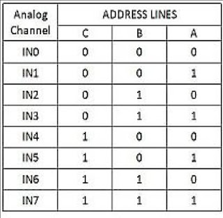
ADDRESS LINE A, B, C
The device contains 8-channels. A particular channel is selected by using the address decoder line. The TABLE 1 shows the input states for address lines to select any channel.

Address Latch Enable ALE
The address is latched on the Low – High transition of ALE.

START
The ADC’s Successive Approximation Register (SAR) is reset on the positive edge i.e. Low- High of the Start Conversion pulse. Whereas the conversion is begun on the falling edge i.e. High – Low of the pulse.

Output Enable
Whenever data has to be read from the ADC, Output Enable pin has to be pulled high thus enabling the TRI-STATE outputs, allowing data to be read from the data pins D0-D7.

End of Conversion (EOC)
This Pin becomes High when the conversion has ended, so the controller comes to know that the data can now be read from the data pins.

Clock
External clock pulses are to be given to the ADC; this can be given either from LM 555 in Astable mode or the controller can also be used to give the pulses.

ALGORITHM
Start.
Select the channel.
A Low – High transition on ALE to latch in the address.
A Low – High transition on Start to reset the ADC’s SAR.
A High – Low transition on ALE.
A High – Low transition on start to start the conversion.
Wait for End of cycle (EOC) pin to become high.
Make Output Enable pin High.
Take Data from the ADC’s output
Make Output Enable pin Low.

The total numbers of lines required are:
Data lines: 8
ALE: 1
START: 1
EOC: 1
Output Enable: 1

I.e. total 12 lines. You can directly connect the OE pin to Vcc. Moreover instead of polling for EOC just put some delay so instead of 12 lines you will require 10 lines. You can also provide the clock through the controller thus eliminating the need of external circuit for clock.


Calculating Step Size
ADC 0808 is an 8 bit ADC i.e. it divides the voltage applied at Vref+ & Vref- into 28 i.e. 256 steps.

Step Size = (Vref+ - Vref-)/256

Suppose Vref+ is connected to Vcc i.e. 5V & Vref- is connected to the Gnd then the step size will be

Step size= (5 - 0)/256= 19.53 mv.

Calculating Dout.
The data we get at the D0 - D7 depends upon the step size & the Input voltage i.e. Vin.
Dout = Vin /step Size.
If you want to interface sensors like LM35 which has output 10mv/°C then I would suggest that you set the Vref+ to 2.56v so that the step size will be

Step size= (2.56 - 0)/256= 10 mV.

So now whatever reading that you get from the ADC will be equal to the actual temperature.

PROGRAM
Here is a program for interfacing the ADC to microcontroller, as stated above I have assumed that the OE pin is connected to Vcc & the clock is given by the controller. This program selects channel 0 as input channel reads from it & saves in the accumulator.
adc_a bit p2.0
adc_b bit p2.1
adc_c bit p2.2
adc_start bit p2.3
adc_ale bit p2.4
adc_clk bit P2.5

Org 0000h
clr ale
clr start

clr adc_a ;
clr adc_b ;Select Channel 0
clr adc_c ;
call delay_small
setb adc_ale ;ale pin high
call delay_small
setb adc_start ;start pin high
call delay_small
clr adc_ale ;ale pin low
call delay_small
clr adc_start ;start pin low
call delay_long
mov a,P1
loop:
ajmp loop

delay_small:
mov r0,#10
l1_delay_small:
cpl adc_clk
nop
nop
nop
nop
nop
nop
djnz r0,l1_delay_small
ret

delay_long:
mov r0,#40
l1_delay_long:
cpl adc_clk
nop
nop
nop
nop
nop
djnz r0,l1_delay_long
ret

End

References:
  1. http://www.dnatechindia.com/
  2. http://en.wikipedia.org

Sunday, March 1, 2009

Counting Type ADCs - 3


Analog to Digital Converts
By Ibrahim Kamal

The Software
The software to be loaded on a microcontroller to perform the task of converting analog signals to digital ones is very simple; The pins P3.0 and P3.1 are both set to Logic 0, and the value of port 2 (which is connected to the first 8 bits of the DAC) is gradually incremented. After each increment the pin P3.7 is checked. Whenever P3.7 is low (logic 0) that means that the generated Analog signal corresponds (with one bit accuracy) to the measured analog signal, and consequently corresponds to the last counted digital value in the micro-controller. In order to extend the resolution from 8 bits to 10 bits, the value of the pins P3.0 and P3.1 is increased each time Port 2 overflows. This way, the precision of this converter is 5 / 1024 = 0.005V, and you can freely increase the precision by increasing the number of bits.

Here is an example C code for the 8051 micro-controller to read the voltage from the above schematic.

While (1){
done = 0;
P3_0 = 0;
P3_1 = 0;
P3_7 = 1; //set P3_7 as input
P2 = 0; //Start counting from 0
delay(100);
while (P2 < 255){
P2++;
delay(100); //Slow down the process, to be compatible with
if (P3_7 == 1){ //the response time of the Op-Amp.
done = 1;
break;
}
}
if (done == 0){
P3_0 = 1;
P3_1 = 0;
P3_7 = 1;
P2 = 0;
while (P2 < 255){
P2++;
delay(100);
if (P3_7 == 1){
done = 1;
break;
}
}
}
if (done == 0){
P3_0 = 0;
P3_1 = 1;
P3_7 = 1;
P2 = 0;
while (P2 < 255){
P2++;
delay(100);
if (P3_7 == 1){
done = 1;
break;
}
}
}
if (done == 0){
P3_0 = 1;
P3_1 = 1;
P3_7 = 1;
P2 = 0;
while (P2 < 255){
P2++;
delay(100);
if (P3_7 == 1){
done = 1;
break;
}
}
}
if (done == 1){
bit8 = P3_0;
bit9 = P3_1;
voltage = ((P2 + (bit8 * 256) + (bit9 * 512))*conversion_factor);
}

The variable 'conversion_factor' in the code represent a factor that relates the counted value to the corresponding voltage, and is easily obtained using some trials and errors. Noting that the relation between the counted value and the corresponding voltage is linear, it's easy to find this factor based on only 2 readings.

References:
  1. Counting Type ADC, Analog to Digital Converter, http://www.ikalogic.com/
  2. http://en.wikipedia.org